Thyristor Why Does Current Continue to Flow After Firing Signal Turns Off
The word commutation corresponds to an act of transferring current from one path to another. Thyristor Commutation refers to the process of turning the thyristor off. There are several ways utilizing which the thyristor gets commutated which is known as thyristor commutation techniques.
We know that once a thyristor gets turned on after the application of gate pulse then even after the removal of gate pulse, current continues to flow through the device. This state is known as forward conduction mode and bringing a thyristor to forward blocking mode from forward conduction mode is known as defined as turning off of the thyristor.
What is a Thyristor?
A thyristor is a four-layer and three-junction semiconductor device that acts as a bistable switch through which conduction takes place only when it is triggered by the use of a gate signal.
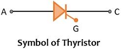
Symbolically, a thyristor is represented as:

It is sometimes called SCR (Silicon Controlled Rectifier) because it is constructed using silicon and offers controlling in rectification action as it offers very low resistance in forward direction and very high resistance in the backward direction. It is different from a diode in a way that forward current from anode to cathode does not begin to flow until and unless a proper gate triggering pulse is provided at the gate cathode terminal.
Its three modes of operations are:
- Reverse Blocking Mode
- Forward Blocking Mode
- Forward Conduction Mode
Commutation of Thyristor
SCR operates as a switch because it swings between on-state and off-state. It is the basic principle of thyristor operation that it gets on only when there is a triggering pulse at the gate cathode terminal of the circuit. During the turn-on condition of the thyristor, the thyristor exhibits forward conduction whereas at this time the turn-off characteristic of the device is ceased. Once conduction has started then even after the removal of the triggering pulse, the device continues to conduct. Hence, a thyristor cannot get turned off by itself. So, the question arises –
How the device can be commutated?
Commutating a thyristor is the process of turning the thyristor off. Using the principle of commutation, thyristor gets its use in controlling operations. It either acts in open circuit condition i.e., off state, or closed circuit condition i.e., on state. A thyristor on its own fails to handle the amount of voltage or current flowing through it. Thus, the only way by which voltage and current can be controlled when switching between on state and off state is done is in accordance with proper commutation.
We know that after getting on once, there is no control of the gate over the device. Thus, we must externally go for commutation. To turn the thyristor off the necessary conditions are:
- The value of anode current should bring back below holding current (Current Commutation),
- The anode terminal must be at low potential with respect to the cathode terminal (Voltage Commutation).
It is to be noted here that the applied reverse potential to the device must be applied for at least the duration required to turn off the SCR. Else, when a positive gate pulse will be applied then the device will begin to conduct even in the absence of a gate signal.
Similarly, anode current should be below the holding current for a definite amount of time which is equal to the turn-off time of SCR. Otherwise, if anode current gets increase then without the presence of a gate signal the device will be in conducting state.
Using commutation circuits, we can fasten the turning off of the device.
Thyristor Commutation Techniques
The classification of thyristor commutation is based on the circuit configuration and the way anode current is reduced to zero. In general, commutation is broadly classified into two categories:
- Natural Commutation
- Forced Commutation
Let us now understand each type.
1. Natural Commutation: This type of commutation does not need external circuitry for the purpose of commutation rather the supply ac input acts as a source of commutation voltage. Its basic principle of operation is that here alternating current of reverse nature is considered to affect the flow of current through the SCR.
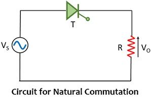
To understand this, consider the circuit shown below:

We are aware of the fact that the alternating current exhibits the nature of crossing zero points after every half cycle. So, once the positive half cycle when current reaches the natural zero-crossing after which voltage of opposite polarity will appear as input. This voltage is utilized to turn the device off. It is also known as line commutation.
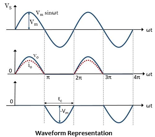
Here during the positive half input, in the presence of gate signal, the drop across the thyristor is equivalent to zero due to forward biased condition. Hence the overall applied input will appear at the output. At the end of the positive half ac signal, the anode current naturally becomes 0. Furthermore, at this instant when the negative half of ac input is provided then the drop across the SCR will not be zero and so it comes in a blocking state, and the device gets turned off.
The waveform representation of input and load voltage is represented below:

As here, after each half cycle when the current becomes 0, so this property of ac input signal is utilized and is regarded as natural commutation.
2. Forced Commutation: This type of commutation requires an external circuit to commutate the thyristor. The external circuit that commutates the device helps in reducing the forward current to zero up to a sufficient time duration so that the complete charged carriers must be removed. This technique is applied in dc circuits is due to the absence of ac input natural commutation does not take place because of unchanged polarity.
The components involved in the commutating circuit are regarded as commutating components.
The basic principle of operation adopted in this type of commutating technique is that by the use of an external circuit, a reverse voltage is produced across the device.
There is a classification of forced commutation given as:
- Class A or Load Commutation
- Class B or Resonant Pulse Commutation
- Class C or Complementary Commutation
- Class D or Impulse Commutation
- Class E or External Pulse Commutation
The basis of this classification is the arrangement of commutating components in the circuit and the way in which the current is made zero.
grahamancomettiody.blogspot.com
Source: https://electronicscoach.com/thyristor-commutation-techniques.html
0 Response to "Thyristor Why Does Current Continue to Flow After Firing Signal Turns Off"
Postar um comentário